


Descripción
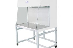
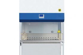
Cabinet Filtration System
Ambient air is pulled through front grille to create inflow, without going into the work surface. Inflow is joined by half of the downflow, to create front air curtain that is fine-tuned to create a large performance envelope. The combined air stream travels through the back air column towards the blower.
Approximately 1/3 of the air in the common plenum is exhausted through the ULPA filter to the room. The remaining 2/3 of the air is passed through the downflow ULPA filter and into the work area as a vertical laminar flow air to create ISO Class 3 work surface and prevents cross contamination.
Near the work surface, the downflow splits. About Half goes to the front grille, and half goes to the rear grille. A small portion enters the the side capture zones to prevent dead air corners (small blue arrows).
The design was optimized to give large performance envelope, that provides operator and product protection at wide Inflow and Downflow variation from the Nominal point.
TECHNICAL SPECIFICATION
Class II, Type A2: BSC-A2-II2
Nominal Size: 1.2 meters ( 4′)
External Dimensions *(W x D x H): 1420 x 810 x 1640 mm / 56.0″ x 31.9″ x 64.6″
Gross Internal Dimensions(W x D x H): 1270 x 623 x 670 mm / 50.0″ x 24.5″ x 26.4″
Usable Work Area: 0.6 m2 (6.5 sq.ft.)
Tested Opening: 229 mm (9″)
Working Opening: 274 mm (10.8″)
Average Airflow Velocity: Inflow: 0.53 m/s (105 fpm) and Downflow: 0.35 m/s (70 fpm)
Airflow Volume:
Inflow: 555 m3 / h (328 cfm)
Downflow: 822 m3 / h (476 cfm)
Exhaust: 555 m3 / h (328 cfm)
Required Exhaust WithOptional Thimble Exhaust Collar: 764 m3 / h (450 cfm)
Static Pressure For Optional Thimble Exhaust Collar: 49 Pa / 0.19 in H2O
Double ULPA Filter Typical Efficiency: >99.999% for particle size between 0.1 to 0.3 microns per IEST-RP-CC001.3 / H14 per EN 1822
Sound Emission: NSF / ANSI: 49 63 dBA and EN: 12469 60 dBA
Fluorescent Lamp Intensity: > 1000 Lux Ultraviolet germicidal lamps
Cabinet Construction: Electrogalvanized steel with Isocide oven-baked epoxy-polyester powder coating, and Stainless Steel 304 (316 is optional). 1.5 mm (0.06″) / 16 gauge thick
Electrical: 115 VAC 50 / 60 Hz: Full Load Amps 11 A. Heat Load 972 BTU / Hr
Nominal Power Consumption : 285W
Net Weight: 283 kg / 624 lbs
Shipping Weight: 345 kg / 761 lbs
Shipping Dimensions, Maximum (W x D x H): 1550 x 950 x 1900 mm / 61.0″ x 37.4″ x 74.8″
Double electrical socket: Meets microbiological tests according to NSF / ANSI 49, EN12469 and JIS K3800 standards
Cabinet only, excludes optional stand.
Class II Type A2 can be used to handle minute quantities of volatile toxic chemicals and trace amounts of radionucleotides when thimble ducted. Use this option if chemical vapor re-circulation into the work zone is permitted.
General Performance and Certifications
The biological safety cabinet shall comply with the following international standards, and the manufacturer shall provide a certified copy of containment and performance tests equivalent to or greater than specified in the following independent international standards for Class II per NSF / ANSI 49 (USA), JIS K3800 (Japan), SFDA YY-0569 (China), and EN 12469 (Europe).
The cabinet shall protect (a) the operator and laboratory environment from particulates generated within the work zone; (b) the product and process within the work zone from airborne contamination from ambient air; (c) and the product and process within the work zone from cross contamination.
The cabinet shall be tested by KI-Discus test (European Standard EN12469:2000) on statistical sampling basis to validate operator/personnel protection. The retention efficiency for the front aperture shall be not less than 99.999%. Microbiological testing for cabinet performance shall also be performed on a statistical sampling basis.
Each cabinet shall be listed by Underwriters’ Laboratories (UL, CUL) or CE for electrical safety.
Original documentation specific to each cabinet serial number shall be provided with the cabinet and maintained in the manufacturers’ records. Test data verifying all performance criteria shall be available upon request to include: (a) inflow velocity through direct inflow measurement method; (b) downflow velocity and uniformity; (c) filter leak scan with aerosol challenge for both filters; (d) electrical safety.
Filtration System
The cabinet shall have one supply downflow filter and one exhaust filter. For Class II A2: Both filters shall be ULPA per IEST-RP-CC001.3 and H14 per EN1822. For Class II B2: The downflow filter shall be ULPA type per IEST- RP-CC001.3 and H14 per EN1822 H14, and the exhaust filter shall be HEPA per IEST-RP-CC001.3 and H13 per EN1822.
The filters shall be constructed with aluminum frame with mini-pleat media design without aluminum separators; no wood or fiberboard shall be used in the filter assembly.
An integral filter guard shall be affixed to prevent damage to the filter media. On Class II A2, the exhaust filter shall further be protected by staggered exhaust damper.
The filters shall be (a) individually scan tested by the manufacturer, (b) individually scan tested after assembly, and (c) easily accessible for scan testing on site, by means of a dedicated upstream sampling port accessible from within the cabinet.
The supply filter shall be angled and oriented to the 10° cabinet front angle to optimize downflow uniformity over the work surface and improve the front aperture containment.
A removable, perforated metal diffuser shall be installed below the supply filter to optimize airflow uniformity and to protect the downflow filter from damage.
Blower System
The cabinet shall have an energy efficient ECM motor that saves 70% energy compared to conventional AC motor.
The blower/motor system shall automatically maintain stable airflow, despite building supply voltage fluctuation and increased filter loading.
The cabinet shall incorporate Night Setback / Standby Mode, to reduce the blower speed when the cabinet is not being used by the operator, while maintaining containment at static condition, as verified by KI-Discus.
The blower/motor system shall be enclosed within a dynamic chamber shaped steel plenum that is integrated with the removable ULPA / HEPA filters to simplify filter changing. Fabric plenum is not allowed.
The integral damper shall be externally adjustable, without the need to decontaminate the cabinet.
Cabinet Design, Construction, Cleaning
The cabinet shall be of triple wall design whereby all positive pressure plenums handling contaminated air shall be surrounded by negative pressure. No positive pressure areas shall be accessible external to the cabinet. The third wall shall conceal utilities.
The cabinet shall have a one piece stainless steel 304 side and back wall with ≥ ¼” radius back corners to allow easy surface decontamination. Siliconed joints and 90° bends on the back corners are not allowed, because they are hard to clean and can harbor contaminants.
The work tray shall be one-piece, integrated with the front grille, removable, stainless steel grade 304 with 45° angle on all sides, without crevices or joints.
The cabinet shall have a stainless steel grade 304, one piece drain trough with 45° angle on all sides, with smooth polished corners, to enable easier surface decontamination. No 90° angle is allowed on any side of the drain trough.
The closed side wall below the normal sash operating height shall be sealed without perforations, return air slots or concealed areas which can harbor contaminants.
The cabinet shall be free of sharp edges, nonfunctional protrusions, bolts, screws or hardware, and all metal edges shall be deburred.
The cabinet exterior top shall be slanted to discourage placement of foreign objects and to maintain proper exhaust airflow.
Ergonomics and Convenience
The front sash shall be frameless to maximize visibility. Sash glass shall be safety glass.
The sash counterbalance shall be suspended on two high- strength cables, and for safety, the sash shall lock into position in the event one cable becomes detached.
Magnetic, not mechanical, proximity sensors shall work in conjunction with the control system to indicate proper sash position for containment.
Fluorescent lamps shall be mounted behind the control panel module out of the work zone. Electronic ballasts shall be used to eliminate flicker, extend lamp life and reduce heat output.
The UV lamp shall operate via an automatic timer with automatic shut-off to extend the UV lamp life, and shall be interlocked with the blower/motor and fluorescent lights for safety.
The cabinet shall be designed with a 10° angled front to optimize user comfort, reduce glare and maximize reach into the work area.
The front grille shall be angled to prevent airflow blockage by accidental placement of objects.
Penetrations for petcocks and service fittings shall be provided; penetrations shall be offset to improve user access.
The cabinet shall accommodate an optional mounting stand for fixed-height or adjustable height configurations.
The cabinet shall be equipped with arm rest that is raised above the inflow grille to improve comfort and prevent the operator’s arms from blocking the inflow grille. The arm rest shall be made from one piece stainless steel 304 that can withstand decontaminant agents and UV lamp.
Certification, Service and Decontamination
The cabinet shall be approved for both hydrogen peroxide vapor (HPV) and formaldehyde decontamination protocol.
All panels leading to potentially contaminated and/or hazardous areas shall be color coded red.
All components with the exception of blower/motor and ULPA filters shall be located outside of contaminated air spaces to facilitate servicing without the need to decontaminate the cabinet.
All exterior surfaces shall be painted with a permanent antimicrobial inhibitor coating to minimize contamination.
For Cabinets with Microprocessor Control
System: BSC-A2-II2
All cabinet functions shall be managed by a programmable microprocessor control system capable of software updates via Internet / email downloads.
The microprocessor controller shall be centrally mounted on the main control panel, angled down toward the user, for easy access and ADA-compliant.
The controller shall include soft-touch keypad controls and backlit LCD display to control the blower/motor, light, UV lamp, electrical outlet(s) and menu.
The LCD shall be large enough to simultaneously display cabinet model, clock, inflow, downflow, sash status, airflow status, and cautionary message should a deviation from normal operating parameters occur.
The controller shall be user programmable on site, to enable or disable functions such as PIN (personal identification number) access restriction, cabinet start-up protocol, airflow alarm and other microprocessor controlled operations as outlined in the user manual.
When programmed ON, the start-up protocol shall perform an automatic pre-purge and post-purge cycle to ensure proper cabinet operation.
The controller shall include a blower/motor hours meter to display aggregate motor running time to assist in predictive maintenance.
Audible and visual alarms shall be provided for unsafe conditions such as improper airflow or sash opening.
The audio alarm shall be able to be muted by the user at adjustable duration, and after that, the audio alarm is automatically resumed.
Airflow shall be monitored by a temperature compensating, thermistor-based, true air velocity sensor mounted in the cabinet.
The airflow display and alarm system shall be individually calibrated before shipment.
Diagnostics button should be available on the control panel, to easily check the cabinet operating parameters and sensor calibration to assist servicing.
The cabinet shall have field calibration mode that simplifies on-site calibration.
A selectable Quickstart mode should be available to automatically turn the blower and lights on/off by moving the sash window to the correct position.
The BSC shall have RS 232 data output port for remote monitoring of cabinet operating parameters.
TCP/IP converter shall be available as an option, to connect RS 232 to network for remote monitoring.
Built-in zero volt relay contact to signal the exhaust blower or exhaust damper to turn ON / OFF when the cabinet internal blower is turned ON / OFF.
Built-in zero volt relay contact to send signal to building remote alarm when the cabinet internal alarm is activated.
G. For Cabinets with Manual Control System: BSC-A2-II2
The cabinet shall be controlled by simple rocker switches. The switch shall prevent the flourescent lamp and UV lamp from being turned on at the same time
Filter pressure gauge shall be used to continuously monitor the filter plenum pressure
Manually adjustable mechanical UV timer shall be used to control the duration of UV lamp activation to prolong the UV lamp.